Installing the Ring Alarm Retrofit kit in a New Construction home
In this post, I don't plan on going into the entire Ring Alarm platform in great deal. My plan is to focus on the Retrofit kit.
When I moved into my house, all of my security system wiring was bundled up in the wall of my main bedroom closet. There's a Cat5e cable (which would normally be terminated as a phone line and be used for the system to dial out to emergency services), 4x 4-conductor wires (3 of these are for power+data to potential alarm keypads, with one being power+data for a motion sensor), and 18x 22 AWG 2-conductor wire. 18 is the same number of doors and windows I have, which made me think that each cable leads back to a window or door. After playing around with the Ring app and the Retrofit kit, I confirmed that each 22/2 cable is it's own door/window. I bundled the rest of the cables back together and put them back in the wall. available for future use if necessary. (I may be able to utilize that Cat5e cable in the future. The Retrofit kit is powered by 2x CR123 batteries. If I can find the right battery eliminator kit, then I can power that via PoE from my switch rather than having an AC adaptor wall-wart in our closet.)
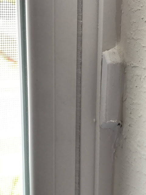
My plan was to sit my amazing Wife in the closet with a multi-meter and have her test each cable for continuity while I go around opening windows & doors to try and map out which cable goes to each door. However, when I tried to test the cables myself, I got no reading on the cables. I decided to hook up one of the cables to the Retrofit kit and use the Ring app to figure it out. After opening up every window and door while looking at the app, I realized that none of my doors and windows had magnets.
Door/window sensors are usually reed switches where two tiny rods are naturally apart, but closed when a magnet is nearby. Having the magnet nearby makes the rods touch, completing the circuit. (What I described is a Normally Closed or NC reed switch. There are also Normally Open or NO sensors, that work on the same principle, but opposite action.). When the circuit breaks, that's when the alarm system goes off. That's when I realized that my security system "pre-wiring" didn't mean it was ready to rock n' roll. Off to Amazon where I got magnets for the windows and recessed door sensors for the doors.
Once we know what cables go where, we can build our zones. The Retrofit kit supports up to 8-zones. If you have more then that, then you'll need to combine zones, or buy another Retrofit kit. It's a cool device, but it's expensive for being essentially a wired-to-wireless Z-wave bridge. The Retrofit kit has 12 screw terminals. Numbered terminals for each of the 8 zones and then 4 shared common terminals. (It looks like 1-C-2-3-C-4-5-C-6-7-C-8). I built my zones by wiring multiple sensors in-series. The conductors in my alarm cabling are Red and Green. For a zone, I would take the first cable and connect the Red conductor to the zone-numbered terminal on the Retrofit kit. Then I would take the Green conductor from the first cable and connect it to the Red conductor of the next cable using a wire nut. Once I had the wires for that zone connected, I would take the final wire's Green conductor and wire it to the Common terminal next to where the Red conductor is wired in. Then, it's a simple rinse & repeat for each remaining zone. For my home, 15 windows will be split into 5 zones while each entry-door will be it's own zone, giving me a total of 8, fully utilizing the Retrofit kit
Once wired up and working, even though the whole thing is in my bedroom closet, I still wanted to make it look pretty. Ring doesn't have any sort of bracket to mount the Retrofit kit over a low-voltage gang box, nor did I find anything similar created by the community (like something I could 3D-print). To tackle this, My initial idea was to use some fabric wire loom like you might use for managing PC cables and route that into a brush plate like you might use behind your TV for running AV cables. However, I decided to go fancier and use Legrand Wiremold products. I used one of their starter boxes to hide my wire nut connections, and some cable raceway routed a short distance to the Retrofit kit. (I promise that the raceway looks much less askew in person. It looks wildly out of level due to the angle of the camera.)


Comments
Post a Comment